How to Improve Construction Site Accuracy: 7 Steps
Table of Contents
- Why Construction Site Accuracy Matters
- Step 1: Plan Your Work Before Construction Begins
- Step 2: Establish Clear Project Goals and Use Approved Drawings
- Step 3: Set Up Site Layout and Surveying With Precision
- Step 4: Implement Construction Site Layout Best Practices
- Step 5: Avoid Common Construction Measurement Errors
- Step 6: Use a Construction Quality Control Checklist
- Step 7: Document, Communicate, and Monitor Progress
- Frequently Asked Questions
Last Updated: October 16, 2026
Why Construction Site Accuracy Matters
Precision on a construction site means catching problems before they become expensive mistakes. A misaligned foundation compromises a structure, incorrect grading causes drainage failures, and utility placement errors create hazardous conflicts. How to improve construction site accuracy starts before the first shovel hits the ground. Here are seven practical steps construction managers use to verify work and prevent costly mistakes.
Step 1: Plan Your Work Before Construction Begins
Planning is where accuracy begins. Before crews arrive, review all project documents: architectural and engineering drawings, site plans and survey data, specifications and material standards, and safety and compliance requirements.
Create a schedule that sequences work logically and identify tasks that depend on accuracy from earlier phases. Grading accuracy affects drainage, which affects foundation placement. Define what “accurate” means for each phase, since trades have different tolerances, and assign clear ownership for verifying measurements, documenting issues, and communicating problems. Without accountability, accuracy problems go unnoticed until they’re expensive to fix.
Step 2: Establish Clear Project Goals and Use Approved Drawings
Your project goals drive every decision on site. Define specific, measurable objectives: timeline targets, budget constraints, quality standards and tolerance levels, safety and compliance requirements, and stakeholder expectations.
Anchor everything to approved drawings, your source of truth. Before work starts, distribute current drawing revisions to all trades, track the active version, and notify affected trades immediately when drawings change. Hold a pre-construction meeting where all trades review the drawings together to identify conflicts and clarify ambiguities. A one-hour meeting can save weeks of rework.
Step 3: Set Up Site Layout and Surveying With Precision
Site layout is the foundation for everything that follows. If the first control point is wrong, every wall, column, and pipe inherits that error.
Build a control network, not just a few stakes
A control network is a set of permanent, interlinked reference points defining horizontal position and elevation across the site. Most projects need two tiers:
- Primary control, three or more points set outside the construction footprint, in stable ground, tied to a known coordinate system and datum.
- Secondary control, points brought in closer to the work as it progresses, established from the primary points by measurement, never by guessing.
Each point should be a physical monument, a steel pin in concrete, capped rebar, or drilled anchor, with its number painted on and its coordinates and elevation recorded in a control register kept with the drawings.
A control point that gets bumped is worse than no control point, because crews keep trusting it. Inspect primary points at the start of each week and after any excavation or heavy delivery near them. Re-observe, do not eyeball.
Tie everything to a stated datum and benchmark
Accuracy problems often trace back to a datum nobody wrote down. Before layout begins, confirm and document the horizontal coordinate system, the vertical datum, and the elevation of at least two benchmarks on or near the site. Put the benchmark elevation on the drawings and on a physical tag at the point. When everyone reads the same number, half the arguments on site disappear.
Use the right instrument for the job
| Task | Typical tool | What it gives you |
|---|---|---|
| Setting primary control | Total station or GNSS receiver | Coordinates tied to the project system |
| Building corners and grid lines | Total station | Angle and distance setout to a few hundredths of a foot |
| Elevations and grades | Digital level or laser level | Height differences over long runs |
| Wide-area existing conditions | Drone photogrammetry or LiDAR | A 3D surface to compare against design |
| Machine guidance | GPS-equipped dozer or excavator | Real-time grade and position in the cab |
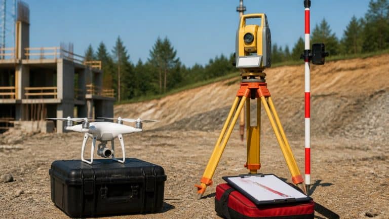
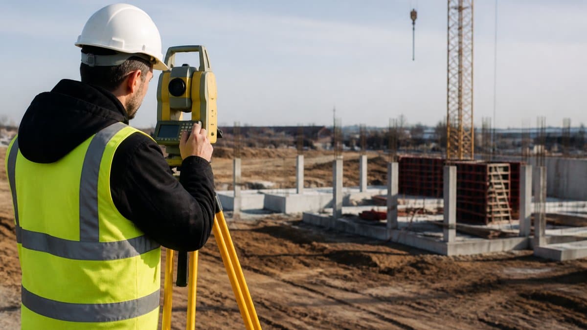
A total station measures angles and distances to a target and computes coordinates, making it the workhorse for setting out. GNSS is faster over open areas but struggles near buildings, trees, and steel. A digital level reads a bar-coded staff electronically, removing most human reading error.
Set out the work, then check it independently
Setting out means marking the design on the ground; checking means proving the marks are right. They are two jobs and should be done by two different people where the budget allows.
A practical sequence:
- Occupy a primary control point and back-sight another. Confirm the instrument is oriented correctly before measuring anything.
- Set the building corners or grid intersections.
- Measure the diagonals of each rectangular area. On a true rectangle they must be equal. A difference of more than a small fraction of an inch over a long span signals a bad corner or a bad instrument setup.
- Close the loop. Measure back to the starting control point and compare the result to its known value. The gap is your closure error.
- Record the setup, the points used, the measured values, and the closure in the field book or app.
Measure the diagonals and the closure every time, even when the layout looks obviously correct. The check costs minutes. A foundation poured in the wrong place costs weeks.
Protect the marks and hand off cleanly
Once layout is set, mark it so it survives. Use offset stakes, hub-and-tack marks, or painted lines on a stable surface. Never rely on a single stake at the corner of an excavation.
Before each trade takes over an area, walk the marks with them and point out the control points, benchmark, and offset references.
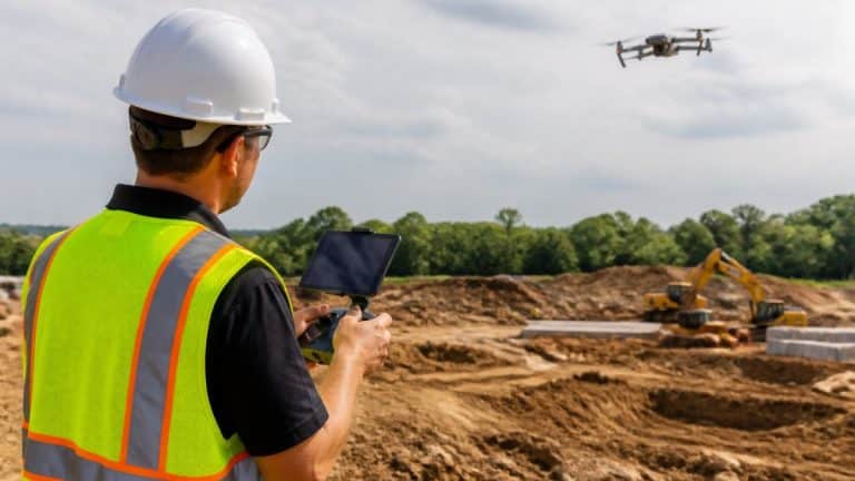
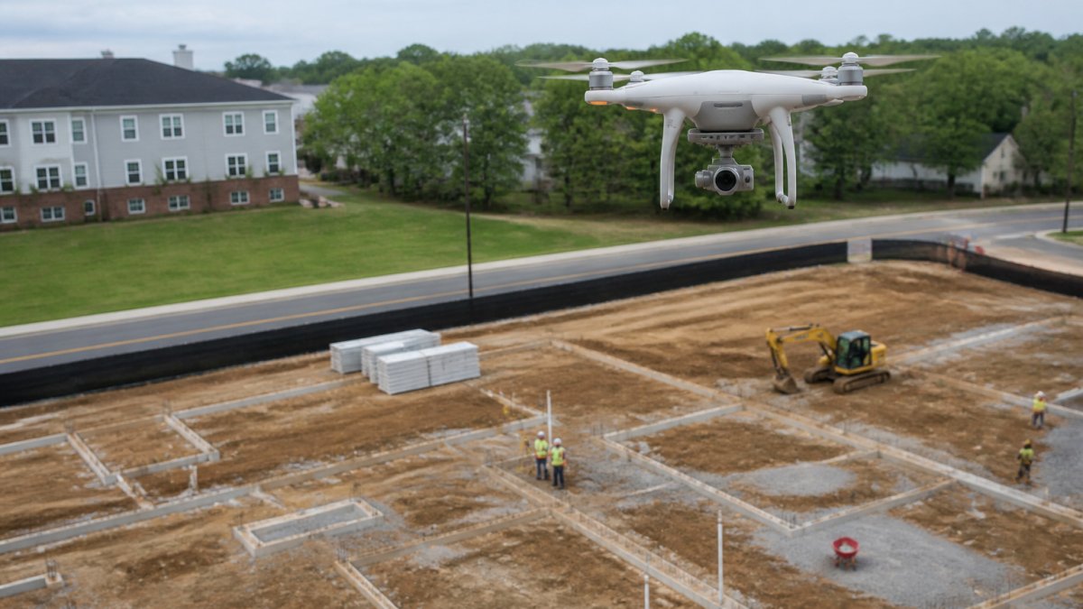
For large or complex sites, drone photogrammetry and LiDAR produce a 3D surface of existing conditions that can be compared against the design model, spotting grading and layout conflicts before they are buried.
Step 4: Implement Construction Site Layout Best Practices
Once your site is laid out, protect that accuracy throughout construction.
Keep survey marks and control points visible and protected so crews don’t disturb them. If a control point moves, re-establish it immediately rather than guessing. Use consistent measurement points, referencing the same control points established in your survey, not different baselines for different tasks.
Verify measurements before and after each phase: excavation against the grading plan, foundation dimensions before pouring concrete, utility placement before backfilling.
Step 5: Avoid Common Construction Measurement Errors
Most measurement mistakes follow predictable patterns. Knowing the causes helps you prevent them.
Using worn or uncalibrated tools. Tape measures stretch with age and laser levels drift out of calibration.
Measuring from inconsistent points. Measure from the same reference every time.
Rounding measurements. Record actual measurements, not rounded values. A quarter-inch difference compounds once you’re placing a dozen components.
Ignoring temperature effects. Steel tape measures expand and contract with temperature. Account for this on precision work.
Measuring at different heights. For vertical measurements, always measure from the same elevation.
Failing to verify measurements. Have a second person check critical measurements.
Step 6: Use a Construction Quality Control Checklist
A checklist only improves accuracy if each line has a number attached. “Verify grading” means nothing; “verify subgrade elevation is within plus or minus half an inch of plan at each grid node” lets a crew pass or fail it on the spot.
Define tolerances before work starts
A tolerance is the acceptable range around a design value, not the same as a measurement’s precision. A tape marked in sixteenths can still set a wall two inches out of position.
Tolerances come from three places: code and standard requirements for structural, life-safety, and accessibility work; manufacturer requirements for the products being installed; and project specifications, which often tighten the above for high-performance buildings.
Write the tolerance next to each checklist item. Where the specification is silent, agree on a number with the designer and record it.
Account for measurement uncertainty
Every measurement carries error from the instrument, the environment, and the person reading it. Ignoring that error is how a crew “passes” a check that later fails.
- Instrument error, a total station or digital level has a stated accuracy. A tape measure stretches with use. Calibrate precision instruments on the manufacturer’s schedule and log it.
- Environmental error, steel tapes expand in heat and contract in cold. Long sight lines through hot air bend. Take critical measurements in stable conditions or apply the correction.
- Human error, misread numbers, wrong target, wrong point occupied. Independent verification by a second person is the cheapest control.
If a measured value is within tolerance but close to the edge, re-measure before accepting it. The re-measure is cheap; the rework is not.
Build the checklist around milestones, not days
Accuracy checks matter most where work gets covered up or handed off. Structure the checklist around those milestones:
| Milestone | What to verify | How to verify | Tolerance source |
|---|---|---|---|
| Control network set | Primary points stable and interlinked | Re-observe from two setups | Survey plan |
| Excavation complete | Subgrade elevation and footprint | Digital level on a grid | Project specs |
| Foundation layout | Corners, diagonals, grid lines | Total station, diagonal check | Structural drawings |
| Before concrete pour | Form dimensions, elevation, embed locations | Tape and level, independent check | Structural drawings |
| Utilities before backfill | Location, depth, slope | Level and tape, as-built sketch | Civil drawings |
| Structural frame | Plumb, alignment, elevation | Total station or laser | Steel or concrete specs |
| Before turnover | As-built dimensions match design | Survey and record drawings | Contract documents |
Each row should name the person responsible and the record proving the check happened.
Turn checks into measurable records
A quality record is only useful if it can be compared over time. Track a small set of indicators:
- Layout deviation, the difference between set-out position and design position, recorded per point
- Survey closure error, the gap when a traverse or loop is closed, recorded per setup
- Rework hours tied to dimensional errors, logged separately from other rework so the cause is visible
- Inspection pass rate, the share of milestone checks that pass on first attempt
- As-built variance, the difference between recorded as-built dimensions and design at turnover
Review these at the weekly coordination meeting. A rising closure error or falling pass rate signals that a control point moved, an instrument is out of calibration, or a crew is working from the wrong revision.
A checklist is a control only when every line has a tolerance, a verification method, a named owner, and a recorded result. Without those four, it is a list of good intentions.
Close the loop on failures
When a check fails, document the deviation, notify the responsible trade the same day, and record the corrective action and re-check. If the same item fails twice, treat it as a process problem and examine the drawing revision, instrument, or handoff.
Step 7: Document, Communicate, and Monitor Progress
Documentation and communication turn measurements into action. Without them, even accurate data goes unused.
Document every measurement and inspection: what was measured, who measured it, when, the result, whether it met standards, and any corrective actions taken.
Communicate findings immediately. If a measurement is out of tolerance, notify the responsible trade the same day.
Use technology to track progress. SkyeTech Aerial captures high-resolution site data showing exactly what’s been built and where, making progress tracking faster and more reliable.
Construction site accuracy isn’t complicated. It’s a system: plan carefully, measure consistently, verify before moving forward, and document everything.
Frequently Asked Questions
What causes measurement errors on a construction site?
Measurement errors stem from several sources: outdated or misread drawings, inconsistent measurement tools, inadequate site setup, and poor communication between teams. Human error in manual surveys, failure to verify dimensions against approved plans, and lack of quality control checkpoints also contribute. Regular verification against original specifications and using consistent measurement methods reduce these errors significantly.
How often should construction site measurements be checked?
Measurements should be verified at critical project phases: before work begins, after major layout work, before material delivery, and before work moves to the next phase. For ongoing accuracy, periodic spot checks every 1-2 weeks catch drift early. More frequent checks on high-precision sections prevent costly rework. Documentation of each check creates a record that protects both quality and accountability.
How can drone surveying for construction improve accuracy?
Drone surveying captures precise aerial imagery and creates detailed 3D models of your site layout and building progress. This allows you to compare actual conditions against approved drawings without manual measurement. Drones detect grading errors, layout discrepancies, and material placement issues early, when they’re cheaper to fix. Regular drone flights document progress and provide objective verification that work meets specifications.
What is the difference between construction accuracy and precision?
Accuracy means your measurements match the approved design specifications. Precision means your measurements are consistent and repeatable. A site can be precise (all measurements agree with each other) but inaccurate (all measurements are wrong in the same way). Both matter: precision ensures consistency, while accuracy ensures the work matches the plan. Quality control requires checking that measurements are both accurate and precise.